Materials used
| No. | Part Name | Image |
|---|---|---|
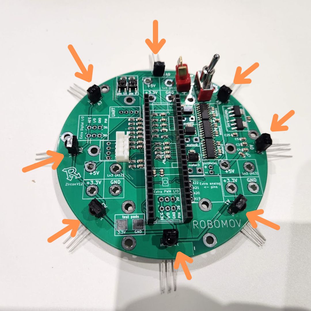
| 1. | Zircon PCB x1 | 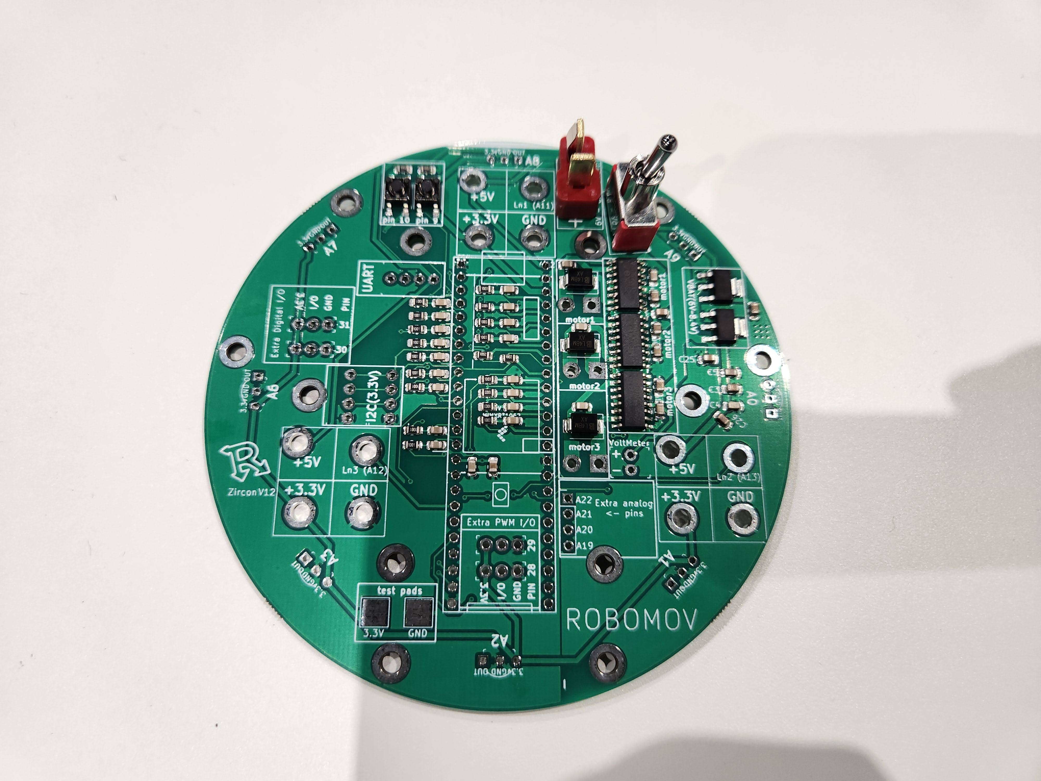 |
| 2. | Female Header Pins x2 | 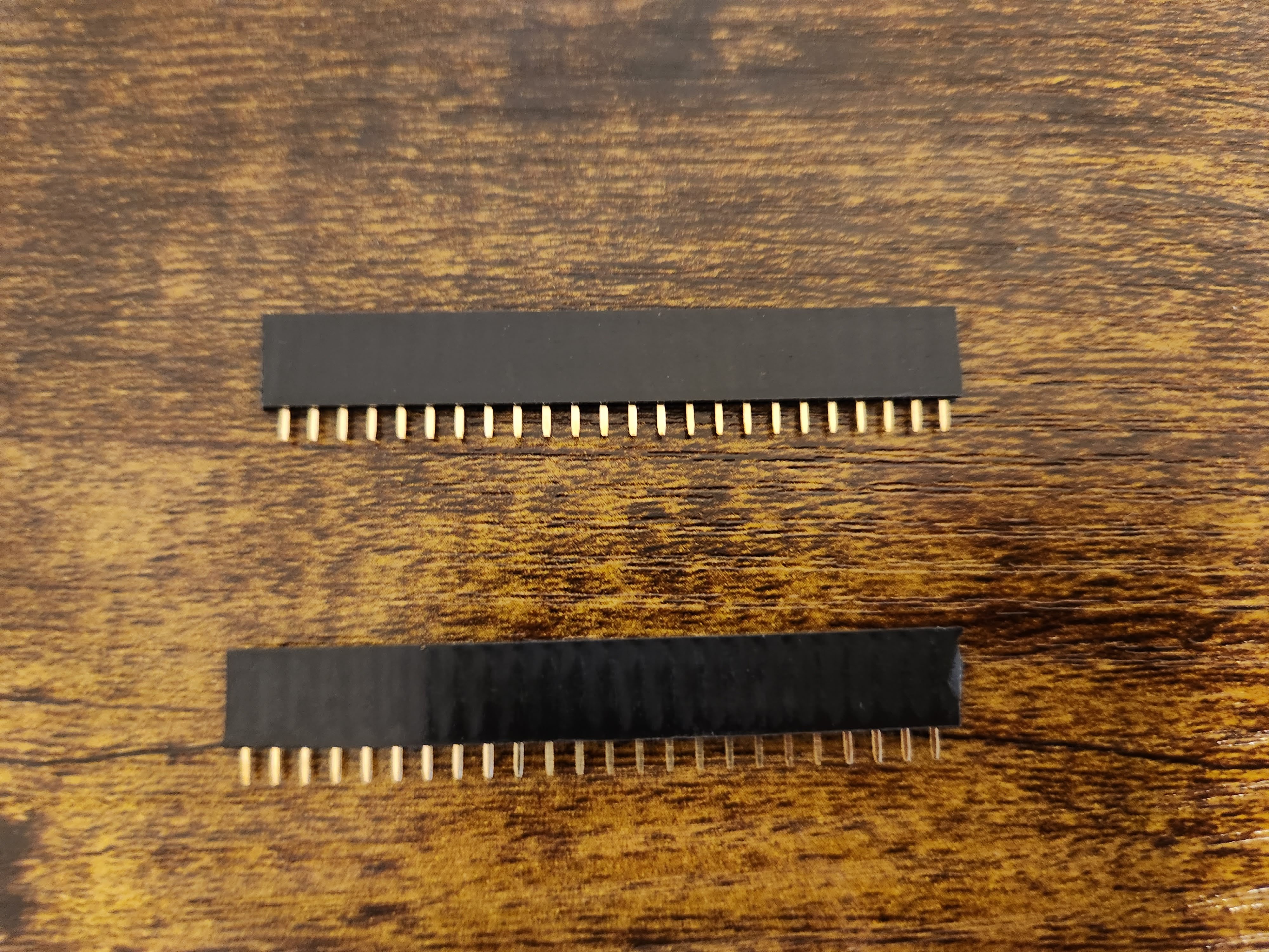 |
| 3. | 4 Pin JST Port x1 | 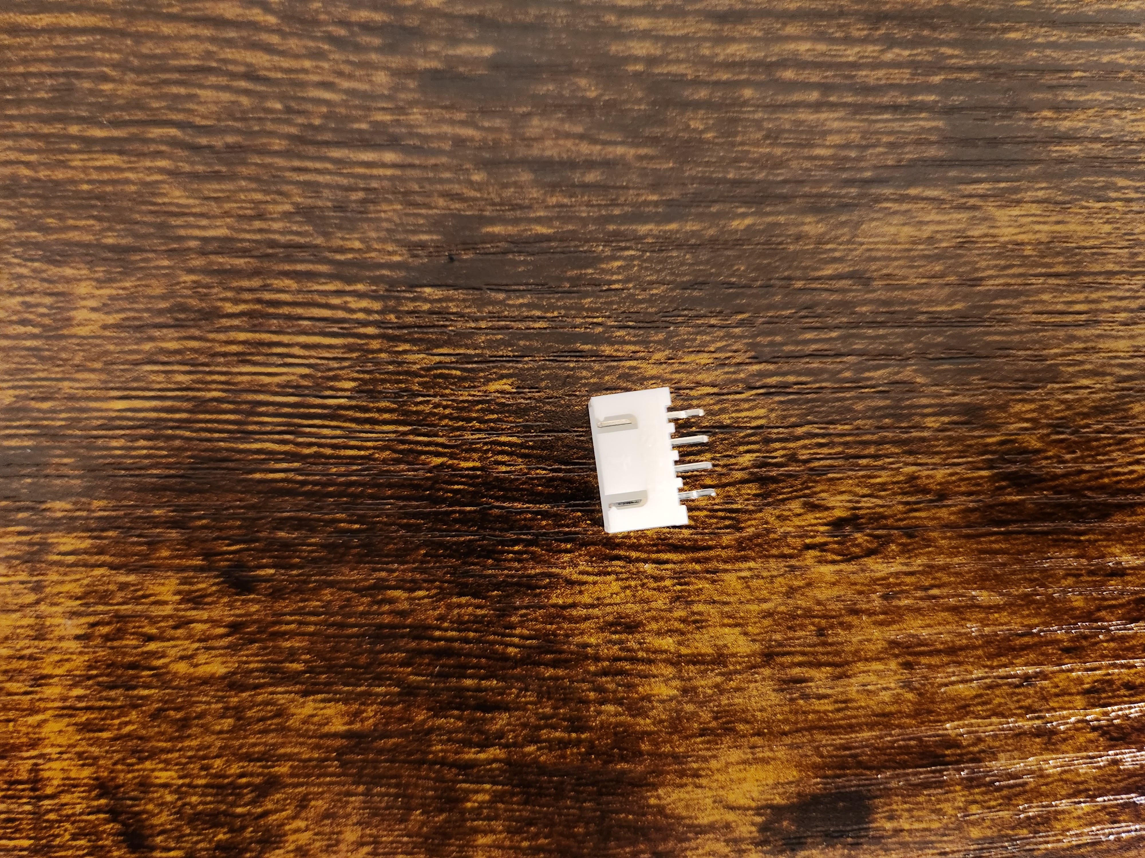 |
| 4. | Ball Sensors x8 | 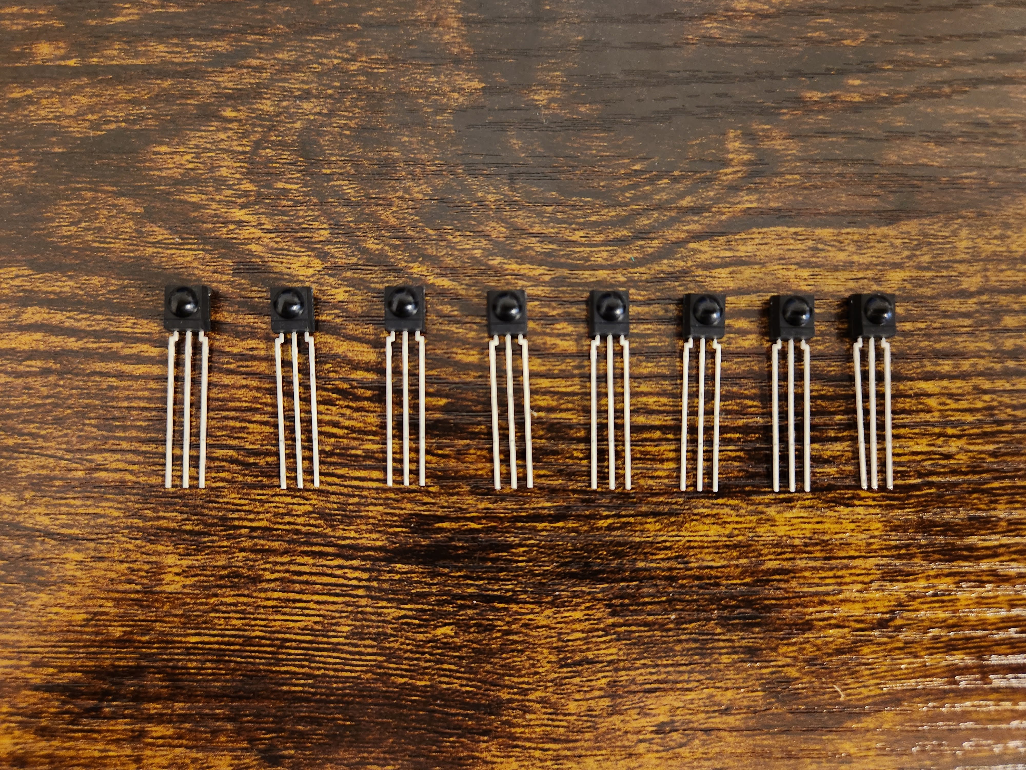 |
Tools needed
| No. | Part Name | Image |
|---|---|---|
| 1. | SOLDERING IRON | 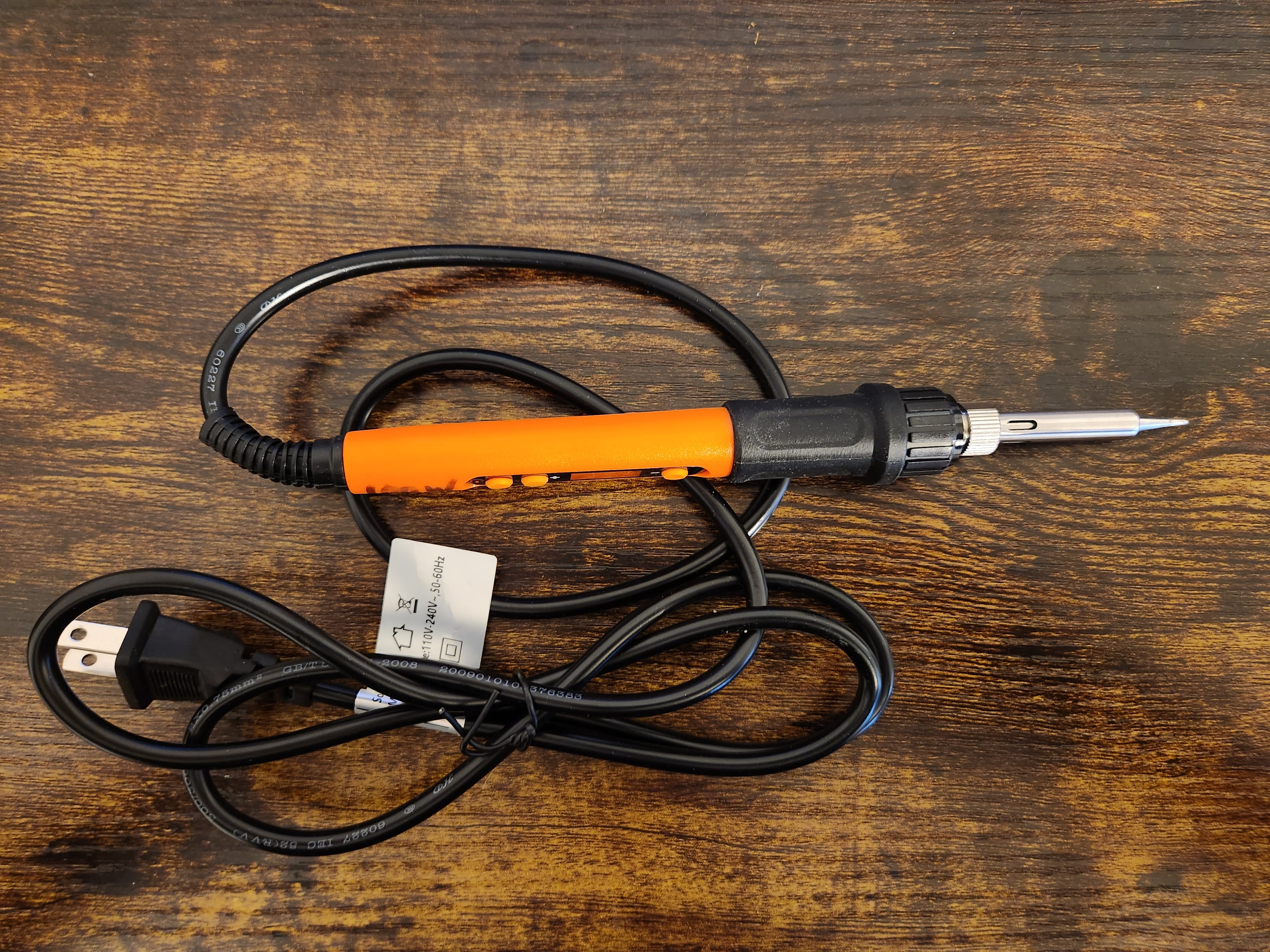 |
| 2. | SOLDER | 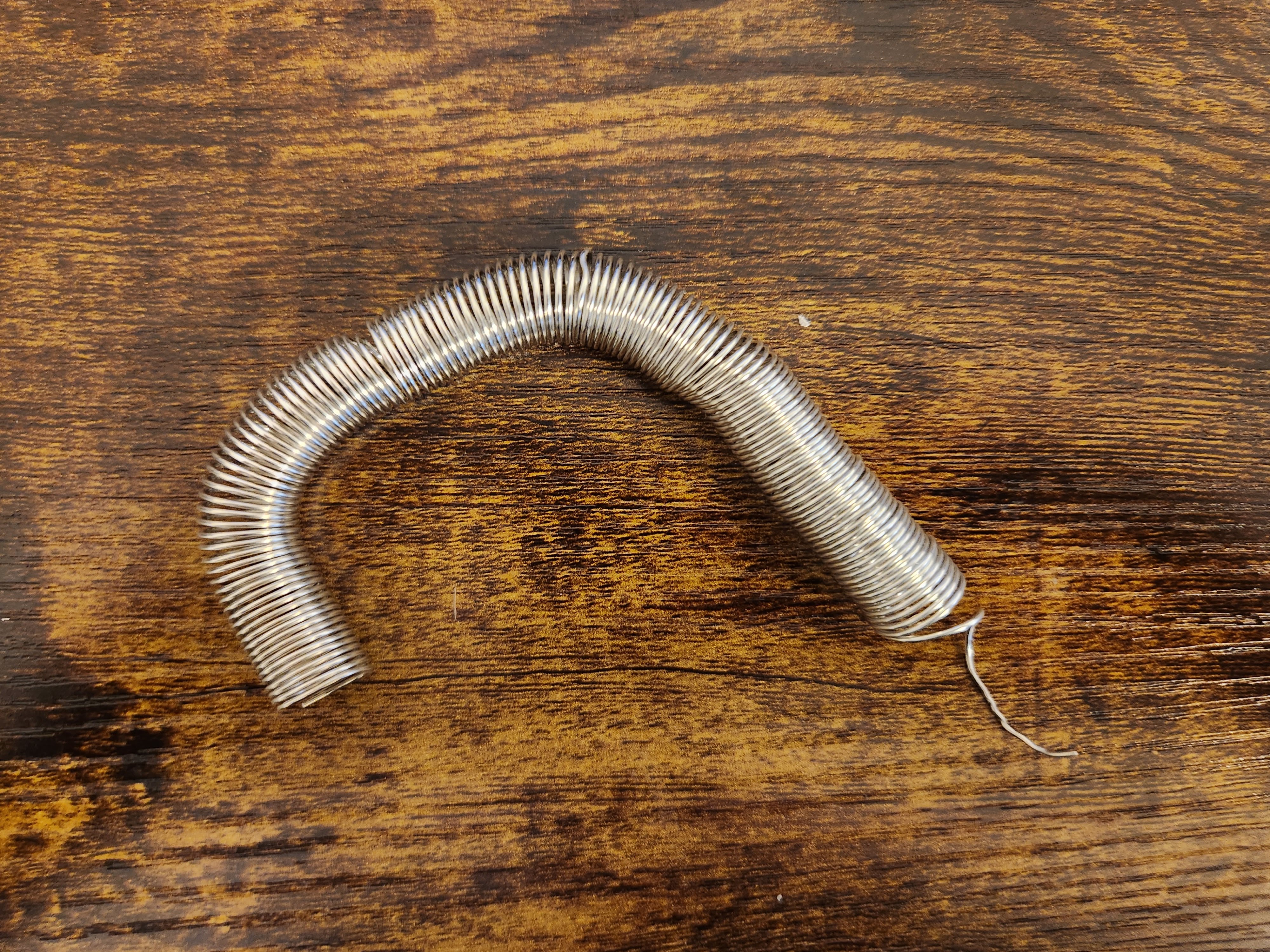 |
| 3. | WIRE CUTTERS | 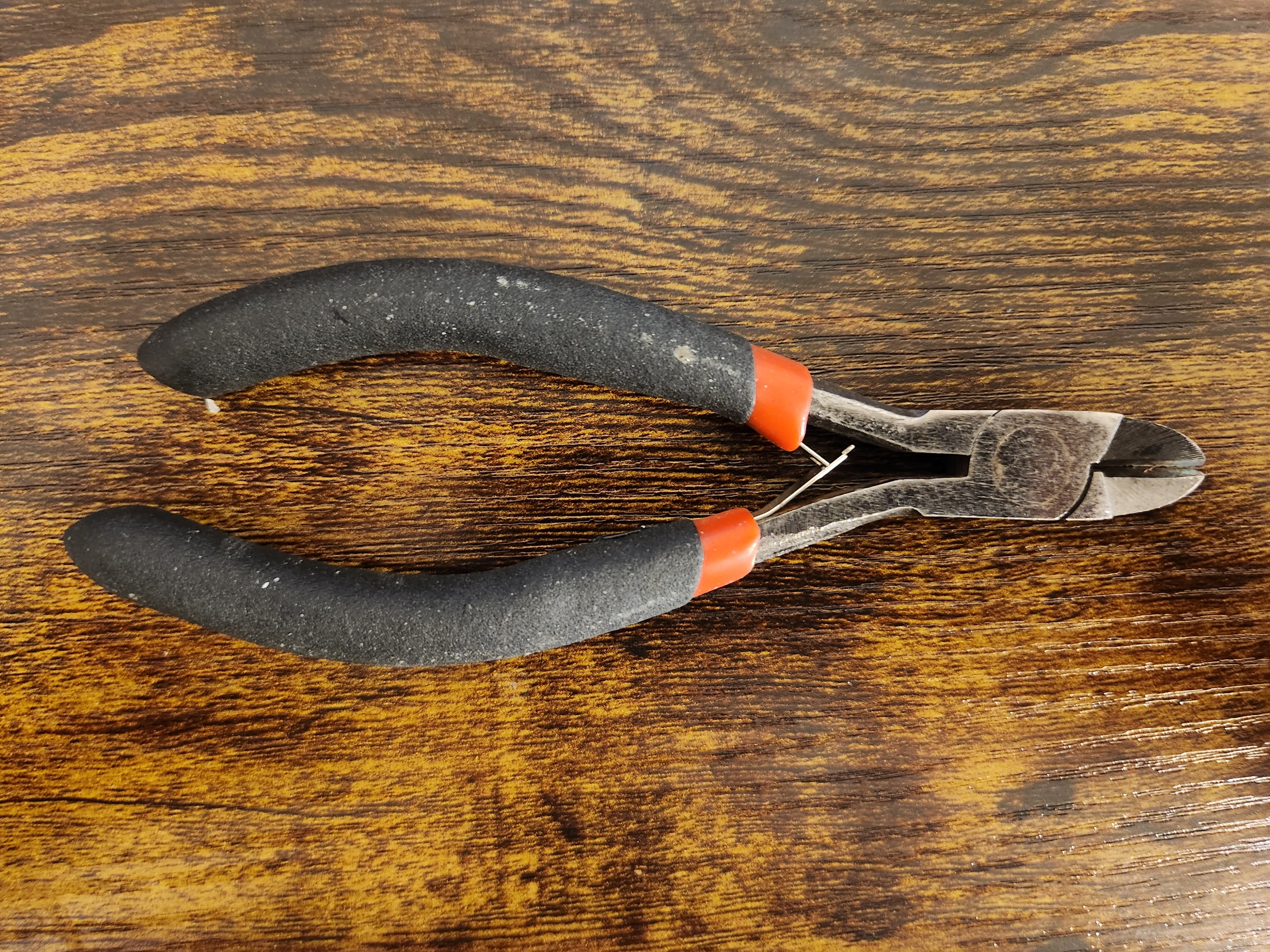 |
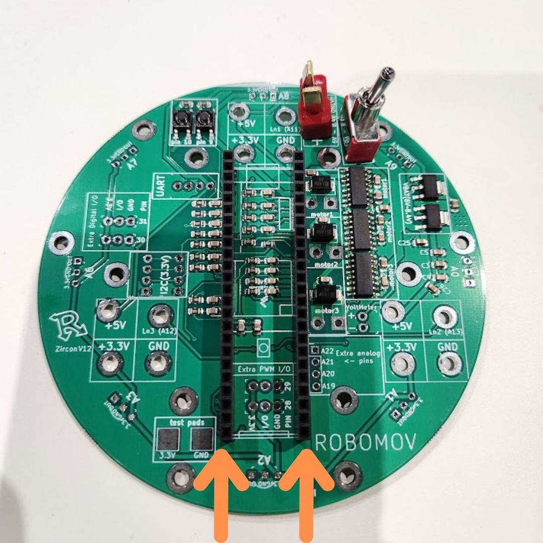
female header pins
Get the two female header pins
and solder them as shown.
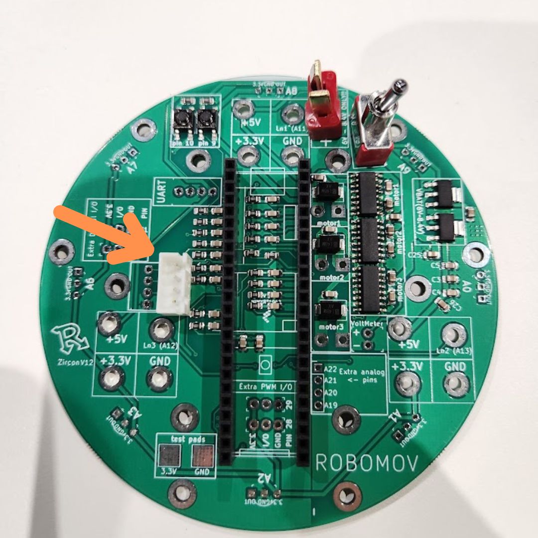
4 pin JST port
Get the 4 pin JST port.
Solder the 4 pin JST port into place. The direction DOES matter so make sure it is exactly like the image.
Get the 8 Infrared sensors.
Insert the Infrared (ball) sensors in the 8 slots equally spaced around the perimeter of the main board and solder them. It helps to bend the pins after inserting, then solder, then clip the extra length of the pins